Datacasting is the one-way delivery of digital data (files, alerts, text, audio, and video) over a television station's broadcast signal, alongside normal programming. Broadcasters use it for emergency alerts, educational content, Internet of Things (IoT) and enterprise data, and rural coverage gaps. In ATSC 3.0 deployments, it works only if the data-carrying physical layer pipes (PLPs) stay clean and robust at the receiver. A PLP is an independently configured logical channel inside one RF transmission. We are the engineering team behind Avateq Corp.'s 24/7 ATSC 3.0 monitoring receivers, so we look at datacasting from the transmitter-site side.
Key takeaways
- One-way by design: Standard data broadcasting sends content simultaneously to many receivers. Any return path requires broadband, cellular, or another uplink.
- No recipient internet required: Receivers pull data directly from the air, so reception works without a broadband connection.
- PLP robustness matters: In ATSC 3.0, data services often target indoor or marginal-signal receivers, where robustness matters more than raw throughput.
- Silent failures: Unlike live television, many data services give no visible warning when delivery degrades, so continuous RF and link-layer monitoring catches problems early.
- Same toolkit across standards: Teletext, ATSC 1.0, DVB, ISDB-T, digital radio, and ATSC 3.0 all solve the same three problems: finding room for data, labeling it so receivers can filter it, and repeating or error-protecting it without a return path. Over time, packaging has shifted toward native IP.
What is datacasting and how does it send data over a TV signal?
Datacasting is the one-way transmission of digital data over a television station's broadcast signal, using the same transmitter, tower, and coverage footprint as the station's programming. Think of it as a broadcast data pipe running next to your video services. "Data broadcasting" is the general engineering term, "broadcast data delivery" typically appears in service descriptions, and "TV datacasting" is common shorthand for the same concept.
How data rides along with your programming
The workflow below follows the null-packet replacement approach documented in the U.S. Department of Homeland Security (DHS) Houston Pilot After Action Report and deployed by South Carolina Educational Television (SC ETV). It represents one proven legacy delivery method in ATSC 1.0, not the way every datacasting system operates.
Source data is packetized, optionally encrypted, and assigned access controls. A multiplexer replaces unused null (padding) packets (PID 0x1FFF) in the MPEG-2 transport stream with datacast packets and combines them with the audio and video streams. The composite signal goes out through the normal transmitter. A compatible receiver identifies the datacast packets, checks authorization, decrypts the payload when encrypted, and passes it to an attached device. Not all datacast content is encrypted.
Ordinary TV viewers see no change, because the datacast packets ride on separate packet identifiers (PIDs) in an MPEG-2 transport stream (or separate IP flows and PLPs in ATSC 3.0) that standard consumer television equipment ignores. That separation lets a station add a data service without disturbing its main programming chain.
How does datacasting work across different broadcast standards?
Datacasting is a delivery method, not a single standard. Every broadcast system that has carried data, from analog teletext to ATSC 3.0, has had to perform the same three jobs. The standards differ in how they implement each one.
The three jobs every datacasting system does
1. Find room for the data. A broadcast channel has fixed capacity, and video and audio traditionally get first claim. Data fills the remainder. In analog TV, that meant unused lines in the vertical blanking interval (VBI), the non-visible region at the top of the frame. In digital TV, it is spare capacity in the multiplex (such as the null packets described above) or a dedicated logical pipe. An ATSC 1.0 channel carries a fixed 19.39 Mbps payload, and in the early DTV era a single HD program could consume roughly 16 to 18 Mbps, leaving data to fit into whatever remained.
2. Label the data so receivers can find it. The sender divides data into small units and tags each one. Signaling tables tell receivers which tags belong to which data service so each receiver keeps what it needs and discards the rest. Those units can be numbered pages (teletext), files and modules (carousels), or IP datagrams.
3. Deliver it without a return path. Because a transmitter cannot hear which receivers missed a packet, broadcast systems rely on two tools. The first is repetition: a carousel broadcasts the same content in a loop so a receiver that misses a block waits for it to cycle around again. The second is error protection: forward error correction (FEC) adds parity or repair data so receivers can detect and rebuild damaged blocks locally without requesting a retransmission.
Datacasting methods by standard
| System | Where the data rides | How it is packaged | Typical uses |
|---|---|---|---|
| Analog teletext and NABTS (1970s onward) | Unused VBI lines of an analog TV signal | Teletext repeats numbered pages in a loop. The North American Broadcast Teletext Specification (NABTS, EIA-516) carried about 15.6 kbit/s per video line and was also used for IP data (RFC 2728) | News and information pages, early IP datacasting such as WebTV |
| ATSC 1.0 data broadcast (ATSC A/90) | MPEG-2 transport stream inside the fixed 19.39 Mbps channel | Digital Storage Media Command and Control (DSM-CC) data carousels for downloads, addressable sections for IP datagrams, and data streaming | Enhanced TV, file downloads, null-packet public-safety services such as the DHS Houston pilot |
| DVB data broadcasting (ETSI EN 301 192) | MPEG-2 transport stream over satellite, cable, or terrestrial links (newer DVB-T2/S2 profiles can also carry IP directly via Generic Stream Encapsulation, GSE) | Multiprotocol Encapsulation (MPE) puts IP datagrams into DSM-CC sections; data carousels and object carousels loop files | Receiver software downloads, IP tunneling over broadcast channels, interactive TV |
| ISDB-T data broadcasting (ARIB STD-B24) | Japan's ISDB-T channel, including the "1seg" mobile segment | Broadcast Markup Language (BML), an XML-based format delivered over a DSM-CC data carousel, alongside dedicated emergency warning signaling | News, sports, weather, and emergency alerts such as Earthquake Early Warning |
| Digital radio (DAB/DAB+ and DRM) | Inside the audio stream (X-PAD in DAB/DAB+) or in a separate data channel (DAB Packet Mode or DRM Main Service Channel data streams) | Small data applications: hierarchical text (Journaline), JPEG/PNG images (Slideshow), and traffic information (TPEG) | Station/song metadata, images, and in-vehicle traffic feeds |
| ATSC 3.0 (A/322, A/330, A/331) | Configurable Physical Layer Pipes (PLPs), each with its own modulation and coding | Native IP: ATSC Link-Layer Protocol (ALP) carries IP packets directly, and ROUTE delivers files with optional application-layer FEC | Rich emergency alerts, automotive/IoT updates, positioning corrections, bulk file delivery |
Two trends stand out. First, every broadcast data system relies on a carousel or similar repetition strategy because a one-way channel cannot ask for retransmissions. Second, packaging has shifted from broadcast-specific formats like teletext pages and BML toward standard IP, allowing standard IP applications to run over broadcast airwaves. The underlying engineering constraints have not changed: RFC 2728, published in 1999 for IP over analog VBI lines, already combined unidirectional header compression and forward error correction. ATSC 3.0 solves those exact same problems at much higher scale using Robust Header Compression in Unidirectional Mode (ROHC-U) and Real-Time Object Delivery over Unidirectional Transport (ROUTE) repair symbols.
Why the carousel matters: a worked example
Suppose a station allocates 1 Mbps of net payload capacity (excluding protocol and FEC overhead) to a carousel sending a 100 MB file. At 800 megabits, one full pass takes 800 seconds, just over 13 minutes. A receiver tuning in at a random moment needs roughly one full pass to collect every block. If a momentary fade drops one block, the receiver waits for that block to come around again, adding up to another 13 minutes.
Application-layer FEC repair data changes that trade-off: although repair symbols slightly lengthen each cycle, a receiver can rebuild missing source blocks as soon as it collects enough total source and repair blocks, without waiting for another full rotation. Raising the carousel bitrate to 5 Mbps cuts one pass to 160 seconds (about 2 minutes and 40 seconds), but consumes capacity from other services. Balancing delivery latency, reception reliability, and shared channel capacity is the central design decision in any datacasting service.
ATSC 3.0 performs the same three jobs, but gives broadcasters far more granular control over each one.
Why ATSC 3.0 changes everything
Under the ATSC 3.0 system architecture (ATSC A/300), the physical layer (ATSC A/322) and link layer (ATSC A/330) replace legacy fixed transport streams with native IP delivery over independently configurable PLPs. ATSC 3.0 datacasting, often referred to as broadcast internet, ties service design directly to the RF chain.
An ATSC 1.0 station transmits one fixed 19.39 Mbps stream with a single reception threshold for every bit in the channel. ATSC 3.0 supports up to 64 PLPs inside one RF channel (with a single service able to use up to 4 PLPs simultaneously). Each PLP carries its own modulation order, Low-Density Parity-Check (LDPC) and Bose-Chaudhuri-Hocquenghem (BCH) error coding, and time interleaving, letting a station tailor robustness per service.
At the link layer, ALP (A/330) encapsulates IP packets directly into baseband frames, and ROHC-U header compression shrinks 28-byte IPv4/UDP headers down to 1 to 3 bytes, which is critical for small, frequent datacast packets such as positioning corrections or telemetry. Above UDP/IP, ROUTE (A/331) manages file carousels and application-layer FEC repair data so receivers reconstruct missed blocks locally without a return request. Beyond single-antenna SISO operation, ATSC 3.0 also supports Layered Division Multiplexing (LDM) and 2x2 cross-polarized MIMO to scale datacast throughput further inside the same 6 MHz channel, a comparison we will explore in Part 2 of this series.
Datacasting vs. broadband: where does it stop?
| Criteria | Datacasting | Broadband internet |
|---|---|---|
| Direction | One-way (downstream broadcast) | Two-way (bidirectional) |
| Delivery model | One-to-many | Primarily individual unicast connections (multicast options exist on managed networks) |
| Scaling cost | Fixed RF cost regardless of receiver count | Scales with concurrent users, backhaul, and cell/access capacity |
| Recipient internet needed | No | Yes |
| Targeting and encryption | Addressing and encryption restrict payloads to authorized devices or groups | Handled per connection/session |
Standard datacasting is one-way. A receiver captures broadcast content but cannot transmit back through the TV channel. Any interactive workflow, delivery acknowledgment, or user-specific request requires a separate return path such as broadband, cellular, or another uplink, a boundary emphasized by Indiana Public Broadcasting Stations (IPBS), DHS, and the National Association of Broadcasters (NAB).
How do broadcasters actually use datacasting?
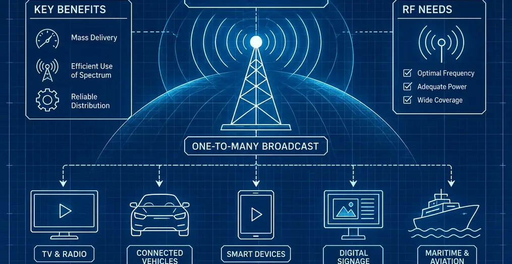
Broadcasters deploy datacasting wherever wide geographic reach, one-to-many efficiency, and zero per-device congestion matter most.
Emergency alerts and public safety
Stations can push wide-area alerts, evacuation maps, building floor plans, and live incident video to first responders and the public, even when cellular networks are congested or out of service. Delivery can target individual units or defined agency groups. The DHS Houston pilot used AES-256 encryption so intercepted broadcasts remain unreadable without authorized keys, while device authorization controls access. In ATSC 3.0, the A/321 bootstrap also includes emergency alert wake-up bits (ea_wake_up) decodable at negative signal-to-noise ratio (SNR) to wake sleeping receivers automatically. Both the U.S. Department of Justice's Office of Justice Programs (OJP) and the National Public Safety Telecommunications Council (NPSTC) frame datacasting as a resilient complement to cellular, land mobile radio, and satellite, not a replacement.
Education without home internet
Teachers package lesson files and assignments, and a public television station broadcasts them over the air. A home datacast receiver captures the files and creates a local Wi-Fi hotspot so Chromebooks and tablets open the materials with no home internet service. SC ETV, IPBS, and EdTech Magazine have documented this model in rural communities. Students still need a separate channel (paper packets, phone calls, or periodic connectivity) to submit completed work.
IoT, enterprise data delivery, and rural broadband supplements
One broadcast transmission can deliver firmware updates, digital signage media, sensor configurations, or large datasets to thousands or millions of endpoints simultaneously without opening individual network sessions. For scale, pushing a 4 GB firmware update to 300,000 connected vehicles over cellular requires 300,000 separate downloads, about 1.2 petabytes of cellular traffic. Over a broadcast channel, the station transmits the 4 GB file once, while cellular or broadband handles lightweight acknowledgments if needed.
In rural areas, datacasting supplements fixed broadband rather than replacing it. Public-safety and broadcast literature cited by OJP and public broadcasters commonly places a single high-power digital TV tower's footprint around 8,000 to 12,000 square miles, compared with tens of square miles for a rural macro cellular site (and far less in urban areas). Actual coverage varies widely with terrain, frequency, power, and receiving antennas.
Positioning and timing
Broadcast Real-Time Kinematic (RTK) services transmit Global Navigation Satellite System (GNSS) correction data over the air. In South Korea, Munhwa Broadcasting Corporation (MBC) demonstrated ATSC 3.0 Broadcast RTK improving standard GPS positioning accuracy from roughly 3 meters to about 3 centimeters (a capability now standardized in South Korea's ATSC 3.0 profile).
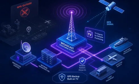
The NAB's Broadcast Positioning System (BPS) goes further, using synchronized ATSC 3.0 signals to deliver nanosecond-level timing as a terrestrial backup to GPS for critical infrastructure such as power grids and telecom networks. BPS has progressed through live verification trials with the National Institute of Standards and Technology (NIST) and utility substations, and continues to move forward in phased development and deployment.
What does datacasting demand from your RF chain?
Data PLPs are only as dependable as the RF signal carrying them. A receiver cannot decode or reassemble packets that the transmitter and propagation path fail to deliver cleanly.
Robust physical layer settings for data-carrying PLPs
ATSC 3.0 data services frequently target fixed indoor, portable, or fringe-area receivers, where PLP robustness matters more than peak bitrate. A robust PLP uses lower-order modulation and heavier LDPC error coding: it requires less SNR at the receiver but carries lower throughput. A high-capacity PLP carries more data but demands stronger reception. The ATSC A/327 Recommended Practice (Guidelines for the Physical Layer Protocol) details these operating-point trade-offs across AWGN, Rayleigh, and Ricean channels.
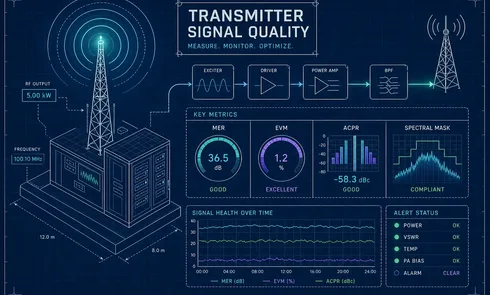
Because ATSC 3.0 multiplexes multiple PLPs with different thresholds in the same 6 MHz channel, composite channel Modulation Error Ratio (MER) can hide trouble on a specific service. Consider a robust PLP delivering firmware updates to rural receivers alongside a high-rate video PLP, or vice versa. Once each PLP is on air, baseline per-PLP MER, per-PLP Link Margin, pre-FEC bit error rate (BER) or LDPC decoding iterations, and constellation quality at each site. Relying solely on post-FEC BER for transmitter-site monitoring is risky because post-LDPC/BCH BER behaves like a step function: it stays flat at zero until the signal is right at the digital cliff. Tracking MER, Link Margin, and decoder effort shows gradual RF drift long before packets drop. If a data delivery fails while RF metrics remain squarely on baseline, you can rule out the RF chain and immediately check the multiplexer, gateway scheduler, packetization, or receiver configuration.
Coverage, antennas, and receiver reality
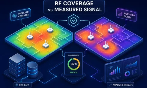
A datacast receiver works anywhere inside usable signal margin, but antenna placement and terrain define the real service contour. NAB highlights relay stations and Single Frequency Networks (SFNs) for filling terrain shadows and strengthening indoor reception. Coverage planning must account for:
- Transmitter power and antenna height
- Frequency band and channel allocation
- Terrain, buildings, and seasonal foliage
- Indoor versus outdoor or mobile reception
- Receiver antenna gain and placement
- Required data rate, carousel cycle time, and reliability
Why a steady transmitter matters more than a perfect day-one setup
Many datacast services have no live television screen showing an operator that delivery has failed. Compatible receivers may provide status dashboards or alarms, but without continuous RF visibility, gradual degradation can go unnoticed. Amplifier nonlinearity, thermal filter drift, interference, or STL glitches can manifest as incomplete files or missed alerts before anyone reports an outage.
A clean commissioning day proves very little about transmitter behavior a month later, especially after weather events, cooling changes, or maintenance. Because RF health alone also does not guarantee that upper-layer files were packaged and scheduled correctly, pair continuous RF monitoring with end-to-end content checks, such as confirming that a periodic test file arrives intact at a reference receiver.
How can you confirm your data PLPs stay healthy 24/7?
You monitor the transmitter output and off-air signal continuously: per PLP, not just by forward RF power or video watchdogs.
Continuous monitoring with Avateq ATSC 3.0 receivers
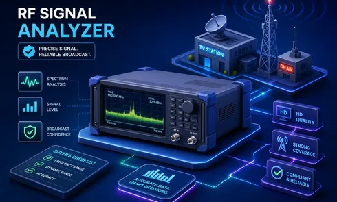
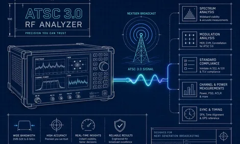
Avateq Corp.'s 24/7 ATSC 3.0 signal analyzers give broadcast engineers continuous physical-layer and link-layer visibility across transmitter sites and coverage areas:
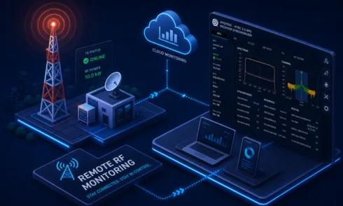
- AVQ1020 and AVQ1022 Transmitter Monitoring Receivers: Built for continuous 1U rack (or portable AVQ1022M) monitoring directly at the transmitter output coupler. They capture an 18 MHz bandwidth for emission mask and shoulder verification alongside per-PLP MER, Link Margin, L1 signaling, and SFN echo analysis, with the dual-chain AVQ1022 adding a second 6 MHz off-air input. Both feature a browser-based Web GUI, Simple Network Management Protocol (SNMP) and Message Queuing Telemetry Transport (MQTT) telemetry, email alerts, and internal logging for offline analysis.
- AVQ200 RF Signal Inspector: A compact 6 MHz, −90 dBm off-air receiver and 12 V DC drive-test monitor for verifying real-world coverage, MER, Link Margin, SFN echoes, and Transmitter Identification (TxID) across the service area, accessible enough to deploy across unmanned translator and gap-filler sites, not just flagship towers.
A simple operational routine
- Baseline per-PLP MER, Link Margin, spectrum shoulders, and L1/ALP signaling at each transmitter site.
- Configure SNMP/MQTT telemetry and email alerts so gradual RF drift reaches engineering before a data pipe hits its SNR cliff.
- Review logged trends after severe weather, antenna work, or exciter/scheduler changes.
Frequently asked questions
Does datacasting need an internet connection?
Not for reception. A return path is required only when an application needs interactivity, acknowledgments, or user-specific requests, and that return path can be broadband, cellular, or even an offline channel depending on the use case.
Can viewers see datacast data on regular TV?
No. Datacast traffic is carried on separate PIDs (in MPEG-2 transport streams) or separate IP multicast flows and PLPs (in ATSC 3.0), so standard consumer TV receivers ignore it.
Is datacasting two-way?
Not over the broadcast RF channel itself. Broadcast delivery is downstream and one-way; two-way workflows pair datacasting with broadband, cellular, or another uplink.
Which broadcast standards support datacasting?
Most digital broadcast standards include data-delivery mechanisms. ATSC 1.0 (A/90), DVB (ETSI EN 301 192 and GSE), ISDB-T (ARIB STD-B24), and ATSC 3.0 (A/322, A/330, A/331) all support data broadcasting, and digital radio standards such as DAB/DAB+ and DRM carry small data applications. Legacy TV standards generally rely on carousels and datagrams inside an MPEG-2 transport stream, while ATSC 3.0 carries native IP over configurable PLPs.
Do you need ATSC 3.0 to datacast?
No. Datacasting predates ATSC 3.0, as analog VBI services and ATSC 1.0 null-packet deployments like the DHS Houston pilot demonstrate. However, ATSC 3.0's native IP transport, ROHC-U compression, ROUTE error recovery, and per-PLP robustness controls make commercial and mission-critical datacasting significantly more flexible and efficient.
Datacasting depends on the signal behind it
Datacasting turns a broadcast television transmitter into a wide-area, one-to-many data pipe that operates without per-device congestion or recipient broadband. Its reliability rests on keeping every data-carrying PLP clean and comfortably above its reception threshold, because unlike a black TV screen, a failing data pipe can drop files silently until someone needs them.
To discuss 24/7 ATSC 3.0 monitoring for your transmitter or off-air sites, contact the Avateq engineering team.
Sources and technical references
- Analog VBI & Legacy Broadcast Data Standards: IETF RFC 2728 (The Transmission of IP Over the Vertical Blanking Interval of a Television Signal, Nov. 1999); ATSC A/90 (ATSC Data Broadcast Standard); ETSI EN 301 192 (DVB Specification for Data Broadcasting); ARIB STD-B24 (Data Coding and Transmission Specification for Digital Broadcasting).
- ATSC 3.0 System, Physical, Link, and Transport Standards: ATSC A/300 (ATSC 3.0 System); ATSC A/321 (System Discovery and Signaling); ATSC A/322 (Physical Layer Protocol); ATSC A/327 (Guidelines for the Physical Layer Protocol); ATSC A/330 (Link-Layer Protocol); ATSC A/331 (Signaling, Delivery, Synchronization, and Error Resilience).
- Avateq Monitoring Solutions: AVQ1020 ActiveCore RF Signal Analyzer, AVQ1022 Dual-Chain RF Signal Analyzer, and AVQ200 RF Signal Inspector.